
A Hydril Dampener is a pressure-control component used on drilling mud pumps and other reciprocating pumping systems. It reduces discharge pulsation before pressure reaches the standpipe, hose, and downhole tools. Inside the chamber, a precharged gas volume compresses as fluid pressure rises. It then expands as pressure falls. This repeated action smooths the flow.
The principle is simple. The operating conditions are not.
Pump speed, mud density, discharge pressure, gas precharge, and diaphragm condition all affect performance. A properly maintained dampener can reduce vibration, protect connected equipment, and improve pressure measurement stability. It does not eliminate every pressure surge. That expectation deserves careful review.
API Specification 7K provides requirements for drilling and well-servicing equipment, including pressure-containing components and safety considerations. The IADC Drilling Manual also emphasizes inspection, maintenance, and controlled operating practices around mud-pumping systems. Broader activity data from the Baker Hughes International Rig Count shows why reliable pressure equipment remains important across land and offshore drilling operations. These sources do not replace the manufacturer’s service instructions, but they provide useful industry context.
In the field, technicians may inspect a Hydril Dampener beside a vibrating mud pump, checking for abnormal noise, leakage, damaged elastomers, or unstable pressure readings. Precharge verification requires the correct gas, calibrated instruments, and an isolated, depressurized system. Small errors can create large consequences. Manufacturer specifications must govern final decisions.
Understanding how the dampener stores and releases energy helps engineers diagnose pulsation, select maintenance intervals, and judge system behavior more accurately. The device is compact. Its influence is substantial. Yet performance depends on installation quality, disciplined inspection, and honest interpretation of operating data.
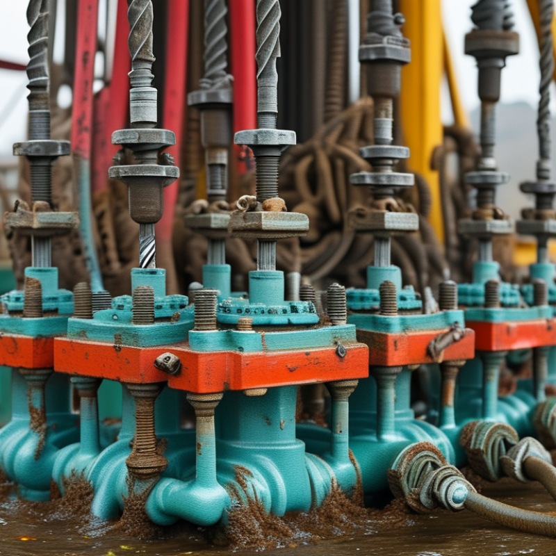
A Hydril dampener is a pressure-control device used with reciprocating mud pumps. It reduces pressure pulsation before drilling fluid reaches the standpipe and surface hoses. The unit usually contains a gas-charged chamber, bladder, or piston. When pump pressure rises suddenly, the chamber absorbs part of the surge. When pressure falls, it releases stored energy. This creates a steadier flow.
Its main location is the discharge side of a drilling mud pump. Crews may also use similar dampeners in cementing units, well-servicing systems, and high-pressure fluid-transfer lines. These locations face repeated pressure changes, vibration, and abrasive fluids. A dampener can protect gauges, valves, hoses, and pipe connections. It can also improve measurement stability. That matters during controlled drilling operations.
The wider need is clear. The U.S. Energy Information Administration reported about 12.9 million barrels of daily crude production in the United States during 2023. Such output depends on reliable pressure equipment across many active wells. API Specification 7K provides requirements for drilling and well-servicing equipment, including pressure-related safety considerations. However, a dampener is not a cure-all. Incorrect gas precharge, damaged elastomers, or blocked fluid passages can reduce performance. The weak point is often maintenance. A quiet pressure line may still hide internal wear. Engineers should compare gauge readings, vibration trends, and inspection records before changing operating settings.

A hydril dampener reduces pressure pulsations in drilling and process systems. It usually sits near a pump discharge line. Its main body is a strong pressure vessel designed for repeated loading. Inside, a flexible bladder or diaphragm separates gas from pumped fluid. The gas compresses when fluid pressure rises, then expands as pressure falls. This cushions the flow and reduces vibration in connected pipes.
The bladder is the working heart of the assembly. A precharge valve controls the gas charge, while a flange or cover secures the internal parts. Some units include a pressure gauge, isolation valve, and safety relief device. The fluid connection must match the pipe size and pressure rating. Even a clean-looking housing can hide fatigue damage. That detail is easy to miss.
Check the precharge pressure when the system is isolated and fully depressurized. Use the specified dry gas and accurate test equipment. Inspect the bladder for cracks, swelling, or hardening during maintenance. A gradual pressure loss may indicate leakage or incorrect valve seating. Never treat unusual vibration as normal. Record pressure readings and inspection dates, although records are often incomplete in busy workshops. The exact component layout can vary, so verify dimensions and limits against the equipment manual before replacement or servicing.
A drilling-fluid dampener is installed near a reciprocating pump’s discharge line. Its job is to absorb pressure pulsations before they travel through pipes, valves, and surface equipment. Inside, a gas chamber sits behind a flexible diaphragm or bladder. When the pump stroke raises fluid pressure, the chamber compresses the gas and stores part of that energy. As pressure falls, the gas expands and pushes fluid back into the line. This rapid exchange smooths the pressure curve. The result is steadier flow, less vibration, and lower stress on connections. Not silent, though.
In practical maintenance, technicians check the precharge with suitable instruments while the fluid side is isolated and depressurized. A low precharge can reduce protection; excessive precharge can limit the device’s working volume. Both conditions may increase pulsation instead of controlling it. The correct setting depends on pump speed, discharge pressure, fluid density, and vessel design. Operators also inspect the diaphragm, mounting bolts, and nearby gauges for leakage or unusual movement. A sudden pressure spike should not be blamed on the dampener alone. Worn valves, trapped gas, restricted lines, or poor timing can create similar symptoms. That detail is easy to miss. A dampener absorbs energy, but it cannot repair an unstable pumping system. Performance records help, although field readings are sometimes incomplete. That uncertainty deserves attention before changing the precharge.
A Hydril Dampener and How It Works
How the Dampening Process Works Step by Step
A drilling-fluid dampener sits near the mud pump discharge line. It contains compressed gas above a flexible diaphragm or bladder. The gas acts like a spring. The pump creates pressure pulses because pistons move separately, not continuously. Industry test papers collected through IADC technical forums commonly report 70–90% lower discharge-pressure variation after correct dampener tuning. Results vary with pump speed, fluid density, and valve condition.
The process begins when a piston accelerates. Pressure rises, and the diaphragm moves upward, compressing the gas chamber. This stores part of the pressure spike. During the piston’s slower return, compressed gas expands and pushes fluid back toward the discharge line. That released energy fills the pressure gap. The gauge needle should move less violently.
Operators then check pre-charge pressure, usually with the pump isolated and fully depressurized. API Spec 7K and related maintenance guidance stress suitable pressure ratings, guards, inspection, and documented testing. A practical field check includes listening for rattling, watching pressure oscillation, and checking gas loss. Small details matter.
Poor pre-charge can make the device almost useless. Too much gas may reduce its effective volume. Too little can cause diaphragm damage. Published service data often links unstable pulsation control with fatigue at valves, fittings, and instrumentation. Still, those figures are not universal. Fluid temperature and solids can change the outcome. The calculation is useful, but field evidence should challenge it.
| Step | Component or Action | What Happens | Pressure and Flow Effect | Practical Result |
|---|---|---|---|---|
| 1 | Connection to the fluid line | The dampener is installed on the discharge side of a reciprocating mud pump, where piston strokes create periodic flow and pressure fluctuations. | The device is exposed to the same pressure pulses as the connected discharge manifold. | The dampener can respond directly to each pressure cycle before the pulse travels farther through the piping system. |
| 2 | Gas precharge | The gas chamber is precharged with dry nitrogen. Nitrogen is used because it is relatively inert and does not support combustion under normal service conditions. | The compressed gas stores energy and establishes the force that opposes rapid fluid-pressure changes. | Correct precharge allows the dampener to absorb pulses without allowing the bladder or separator to operate outside its intended range. |
| 3 | Fluid enters the dampener | When pump discharge pressure rises during a stroke, a portion of the pressurized drilling fluid moves into the fluid side of the vessel. | The incoming fluid compresses the nitrogen gas and temporarily stores part of the pulse energy. | The peak pressure reaching the discharge line is reduced compared with an un-dampened system. |
| 4 | Separator movement | A bladder, diaphragm, or other pressure separator moves as the fluid volume changes, keeping the gas and drilling fluid apart. | The separator transfers pressure changes to the gas cushion while limiting direct gas–fluid contact. | Gas absorption into the drilling fluid is minimized, and the gas chamber remains available for repeated pressure cycles. |
| 5 | Pressure falls between strokes | As the pump piston reverses or moves through a lower-flow portion of its cycle, discharge pressure begins to decrease. | The compressed nitrogen expands and pushes stored fluid back toward the discharge line. | The low point of the pressure cycle is raised, producing a more continuous average flow. |
| 6 | Repeated charging and discharging | The dampener alternately accepts and returns a small volume of fluid during each pump cycle. | The gas cushion acts as a compliant spring, smoothing rapid changes rather than eliminating all pressure variation. | Pulsation, vibration, shock loading, and noise in downstream equipment are reduced when the unit is correctly sized and maintained. |
| 7 | Interaction with the pump system | The dampener works with the pump, discharge manifold, valves, hoses, and other flow-line components as one hydraulic system. | Its effectiveness depends on pump speed, stroke frequency, fluid compressibility, line volume, and the selected gas precharge. | System performance improves when the dampener is matched to the pump’s operating envelope rather than treated as an isolated component. |
| 8 | Inspection and maintenance | Operators check the gas precharge, pressure gauge, connections, separator condition, shell condition, and signs of leakage or abnormal vibration. | Loss of precharge reduces gas volume and changes the dampener’s stiffness, while a damaged separator can allow fluid into the gas chamber. | Routine inspection helps preserve pulsation control and supports safe operation within the rated pressure and temperature limits. |
| Key principle: A Hydril dampener uses a compressed gas cushion and a fluid–gas separator to absorb part of the high-pressure pulse and return stored fluid during the lower-pressure portion of the pump cycle. Actual pressure ratings, precharge values, temperature limits, and maintenance intervals must always follow the equipment design documentation and applicable safety standards. | ||||
A hydraulic drilling dampener absorbs pressure pulses from the mud pump discharge line. A gas-filled chamber compresses when the piston creates a pressure spike. It then expands during the lower-pressure portion of the cycle. This action smooths flow, protects valves, and reduces vibration in the standpipe and surface piping. API Spec 7K provides pressure-equipment guidance, with 5,000 and 7,500 psi classes commonly used as industry reference points. The nameplate rating remains the controlling limit.
Operating limits depend on pressure, temperature, fluid density, and gas precharge. Many field procedures set nitrogen precharge near 60–70% of expected working pressure, but this is not universal. Always follow the equipment calculation and approved maintenance procedure. Never exceed the rated pressure or use compressed air. That shortcut is dangerous. A pressure gauge can appear normal while the bladder or diaphragm is already damaged.
Maintenance requires isolation, depressurization, and verification before removing any cover. Technicians should record precharge pressure, inspect seals, check clamp bolts, and examine the shell for corrosion or cracking. API RP 54 supports controlled energy isolation during drilling maintenance. In practice, inspection intervals should shorten when abrasive mud, high temperature, or frequent pressure cycling is present. These dampeners serve on triplex mud pumps, cementing units, well-service pumps, and high-pressure test systems. The difficult part is judgment. A clean exterior does not prove reliable internal performance.
A hydraulic pulsation dampener uses a gas-charged chamber to absorb pressure fluctuations from reciprocating pumps. The values below are common starting guidelines and must be verified against the pump, fluid, temperature, and vessel rating.
Discharge dampeners are commonly precharged to approximately 50–60% of normal discharge pressure, while suction dampeners are often set higher, around 60–70% of minimum suction pressure. Regular maintenance includes checking nitrogen precharge, inspecting the bladder or diaphragm, verifying relief protection, and confirming that operating pressure and temperature remain within the vessel design limits.
3295 Cobb International Blvd.
Kennesaw, GA 30152
800-367-1377
sale@patiostools.com
© 2023 - Marsh Instruments